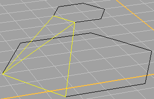
Now we build the surfaces themselves of the turret. We could go back to the good old Surface From 3 or 4 Corner Points tool, but we won't. Instead we're going to use the 3D Face tool, which works in exactly the same way. Make two surfaces to cover one side of the turret, like in the picture. Do a quick Render Preview to make sure that they're facing the right way.
The reason we made only one side is that we can easily duplicate the side to cover all the rest, sort of like mirroring. ![]() With the 2 3D Faces selected, click and hold the Array button to bring up the Array palette, as in the picture.
With the 2 3D Faces selected, click and hold the Array button to bring up the Array palette, as in the picture.
Double-click the perspective viewport title to show the others, turn "Snap" on and any of the "OnSnap" options off, and then in the top viewport click in the center of the hexagons. Rhino will ask up on the command line for the number of elements. Since a hexagon has 6 sides, type 6 and press "Enter". You will then be asked for the angle to fill, with the current angle displayed in parentheses. We want 360, which is the default, so press "Enter" again.

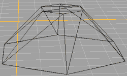
Now the turret is missing only it's top, so turn on OnSnap's "End" and turn off "Snap", and create that from triangular 3D faces as well. The final result should look like the picture.
If you read and understood the sidebar, "Surfaces vs. 3D Faces", you might be wondering why OnSnap's "End" worked to create the top of the turret, when the sides are composed of 3D Faces that don't register with snap tools. The answer is simple. The polylines that defined the top and bottom of the turret are still there, and it was to them that the pointer was snapping, not to the 3D Faces.
(Now comes the part where you wonder what the heck I'm doing.) ;)
![]() See this button up top? It creates what Rhino calls a polysurface in the shape of a box. A polysurface is basically a bunch of surfaces, which can be non-flat, that are grouped or joined together so that they act as one object. We're going to use it because it's simple. It converts horribly, but we will remove it in TS, so there's no worry about how many polygons it adds.
See this button up top? It creates what Rhino calls a polysurface in the shape of a box. A polysurface is basically a bunch of surfaces, which can be non-flat, that are grouped or joined together so that they act as one object. We're going to use it because it's simple. It converts horribly, but we will remove it in TS, so there's no worry about how many polygons it adds.

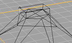
Turn on OnSnap's "End", and turn off "Snap". Make a new layer for the up-and-coming box, called turret01-box (actually, the name is not crucial, but it helps to keep track of which turret it belongs to). Click on the box tool, and then create a box on top of the turret. Snap the box's corners to opposite corners of the turret top, and don't make it very tall. It must be centered over the turret, though. It should look like the picture. The small white squares are where the box's corners are placed.
Ok, ok - I won't keep up the suspense any longer. The box is going to serve as the object that defines the location of the firepoint of the turret. Understand now? No? Well, don't worry - you'll see how it gets used later. :)